| DIMENSION | SIZE | TOLERANCES |
|---|---|---|
|
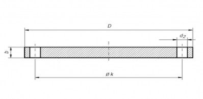
D Outside diameter |
≤ DN 200 | ± 1,0 |
| > DN 200 ≤ DN 300 | ± 1,5 | |
| > DN 300 ≤ DN 400 | ± 2,0 | |
| > DN 400 | ± 2,0 | |
|
d1 Outside diameter of neck |
≤ DN 100 | +0,5 -0 |
| > DN 100 ≤ DN 400 | +1,0 -0,5 | |
| > DN 400 | +1,5 -1,0 | |
|
d1 Bore diameter |
≤ DN 80 | +0,5 -0 |
| > DN 80 ≤ DN 350 | +1,0 -0 | |
| > DN 350 ≤ DN 400 | +1,5 -0 | |
| > DN 400 | +5 | |
|
b Thickness |
≤ DN 10 | ± 0,5 |
| > DN 10 ≤ DN 20 | ± 0,8 | |
| > DN 20 ≤ DN 50 | ± 1,0 | |
| > DN 50 | ± 1,5 | |
|
d3 Neck diameter |
+1 -0 | |
|
h1 Length through hub |
≤ DN 80 | ± 1,5 |
| > DN 80 ≤ DN 250 | ± 2,0 | |
| > DN 250 | ± 3,0 | |
|
S Wall thickness |
≤ DN 100 | +1,0 -0 |
| > DN 100 ≤ DN 400 | +1,5 -0 | |
| > DN 400 | +2,0 -0 | |
|
d4 Diameter of contact face |
≤ DN 80 | +0 -1,0 |
| > DN 100 ≤ DN 400 | +0 -2,0 | |
| > DN 400 | +0 -3,0 | |
|
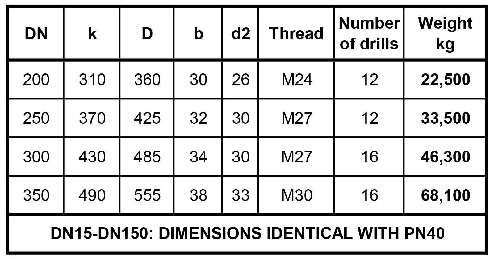
k Diameter of bolt circle |
≤ DN 250 | ± 1,5 |
| > DN 250 ≤ DN 600 | ± 2,0 | |
| > DN 600 | ± 3,0 | |
| Centre-to-centre of adjacent bolt holes | ± 0,4 | |
| Max. eccentricity between bolt circle dia. K and machined facing diameters | +0,8 -0 | |
| Surface parallelism | 1° | |
|
d2 Holes diameter |
≤ DN 300 | +2 -0 |
| > DN 30 | +3 -0 |
| D | Outside Diameter* | Slip-on, Blind and Welding neck flanges | When OD is 24" or less | ±1,6 mm |
| When OD is over 24" | ±3,2 mm | |||
| J | Inside Diameter | Slip-on flanges | 10" and smaller | +0,8 mm |
| 12" and larger | +1,6 mm | |||
| Inside Diameter** | Welding neck flanges | 10" and smaller | +0,8 mm | |
| 12" to 18" | +1,6 mm | |||
| 20" and larger | +3,2 mm -1,6 mm | |||
| g | Diameter of Contact Face | Slip-on, Blind and Welding neck flanges | 1,6 mm Raised Face | ±0,8 mm |
| 6,4 mm Raised Face | ±0,5 mm | |||
| a | Diameter of Hub at Point of Welding | Welding neck flanges | 5" and smaller | +2,4 mm -0,8 mm |
| 6" and larger | +4,0 mm -0,8 mm | |||
| m | Outside Diameter of Hub* | Slip-on and Blind flanges | 12" and smaller | +2,4 mm -1,6 mm |
| 14" and larger | ±3,2 mm | |||
| Diameter of Hub at Base* | Welding neck flanges | When Hub Base is 24" or less | ±1,6 mm | |
| When Hub Base is over 24" | ±3,2 mm | |||
| i | Drilling and facing | Slip-on, Blind and Welding neck flanges | Bolt Circle Diameter k | 1,6 mm |
| Center-to-center of adjacent bolt holes | ±0,8 mm | |||
| mmMax. eccentricity between bolt circle dia. kand machined facing diameters | ||||
| sizes 2½" and smaller | 0,8 mm | |||
| sizes 3" and larger | 1,6 mm | |||
| h | Overall Length of Hub | Slip-on and Blind flanges | 18" and smaller | +3,2 mm -0,8 mm |
| 20" and larger | +4,8 mm -1,6 mm | |||
| Welding neck flanges | 10" and smaller | ±1,6 mm | ||
| 12" and larger | ±3,2 mm | |||
| b | Thickness | Slip-on, Blind and Welding neck flanges | 18" and smaller | +3,2 mm |
| 20" and larger | +4,8 mm |
* This tolerance is not covered by ANSI B 16.5
** Undependent of the tolerances of the measures J and a, the wall thickness shall not be less than 87,5% of the nominal wall thickness
| Dimension | Flange type | Size | Tolerance mm |
|---|---|---|---|
| Outside diameter of neck d1 | 11 | ≤DN 125 | 0 to +3,0 |
| >DN 125 ≤ DN 1200 | 0 to +4,5 | ||
| >DN 1200 | 0 to +6,0 | ||
|
Bore diameter d1 |
01, 02 | ≤DN 100 | 0 to +0,5 |
| >DN 100 ≤ DN 400 | 0 to +1,0 | ||
| >DN 400 ≤ DN 600 | 0 to +1,5 | ||
| >DN 600 | 0 to +3,0 | ||
| Wall thickness S | 11 |
Machined neck
machined or
(both faces)
Neck one face
machined or
unmachined
|
|
| ≤DN 100 |
0 to +1,0
0 to +2,0
|
||
| ≤DN 100 |
0 to +1,5
0 to +2,5
|
||
| ≤DN 100 |
0 to +2,0
0 to +3,5
|
||
|
Outside diameter D |
01, 02, 05, 11, 13 | ≤DN 150 | ±2,0 |
| >DN 150 ≤ DN 500 | ±3,0 | ||
| >DN 500 ≤ DN 1200 | ±5,0 | ||
| >DN 1200 ≤ DN 1800 | ±7,0 | ||
| >DN 1800 | ±10,0 | ||
|
Length through hub h1 |
11 | ≤DN 80 | ±1,5 |
| >DN 80 ≤ DN 250 | ±2,0 | ||
| >DN 250 | ±3,0 | ||
|
Neck diameter d3 |
11 | ≤DN 50 | 0 to -2,0 |
| >DN 50 ≤ DN 150 | 0 to -4,0 | ||
| >DN 150 ≤ DN 300 | 0 to -6,0 | ||
| >DN 300 ≤ DN 600 | 0 to -8,0 | ||
| >DN 600 ≤ DN 4000 | 0 to -10,0 | ||
|
Neck diameter d3 |
13 | ≤DN 50 | 0 to +1,0 |
| >DN 50 ≤ DN 150 | 0 to +2,0 | ||
| >DN 150 ≤ DN 300 | 0 to +4,0 | ||
| >DN 300 ≤ DN 600 | 0 to +8,0 | ||
| >DN 600 ≤ DN 1200 | 0 to +12,0 | ||
| >DN 1200 ≤ DN 1800 | 0 to +16,0 | ||
| >DN 1800 | 0 to +20,0 | ||
|
Flange thickness b |
All types (machined on both faces) | ≤18 mm thickness | -1,3 to +1,0 |
| >18mm ≤50mm thickness | ±1,5 | ||
| > 50 mm thickness | ±2,0 | ||
|
Flange thickness b |
All types (machined on front face only) Type 02 and 04 (un- machined) | ≤18 mm thickness | -1,3 to +2,0 |
| >18mm ≤50mm thickness | -1,5 to +4,0 | ||
| > 50 mm thickness | -2,0 to +7,0 | ||
|
Diameter of bolt circle K |
01, 02, 05, 11, 13 | Bolt sizes M10 to M24 | ±1,0 |
| Bolt sizes M27 to M45 | ±1,5 | ||
|
Center-to-center of adjacent bolt holes |
01, 02, 05, 11, 13 | Bolt sizes M10 to M24 | ±1,0 |
| Bolt sizes M27 to M45 | ±1,5 | ||
|
Eccentricity of machined facing diameters |
01, 02, 05, 11, 13 | ≤ DN 65 | 1,0 |
| > DN 65 | 2,0 |
| Type 01 - Plate Flanges | Type 02 - Plate Flanges | Type 05 - Plate Flanges | Type 11 - Plate Flanges | Type 13 - Threaded Flanges |